PlotBot: Brief

So as time draws on we are getting closer to the start of the new academic year, and of course that means Fresher’s Fair!
At Kent we have several creative societies including SpaceSoc and their “Build a Rocket” sessions, Engineering Soc  with their focus on robotics, and TinkerSoc who want to help people build without limits.
With TinkerSoc it has become somewhat of a tradition to build and showoff a project at the fresher’s fair. In previous years we have had a laser engraver making custom name tags and furbies singing bohemian rhapsody, basically something to grab peoples attention and imagination.
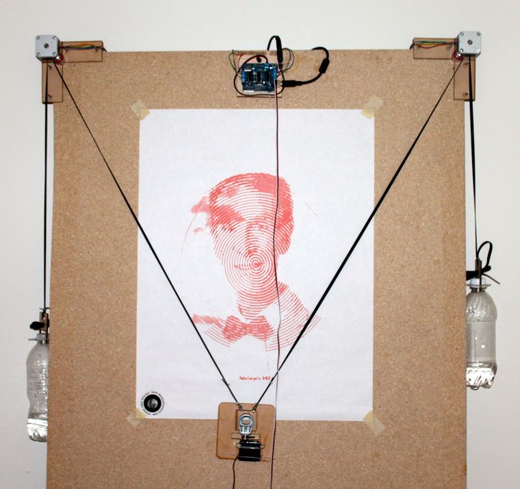
Having seen a number of vertical plotters online I have decided now is the time to build one.

The standard vertical plotter is made up of 2 stepper motors, a servo, a motor controller and a microcontroller. By providing a stream of polar coordinates to the robot, the two motors can be wound in and out to move a pen across the whiteboard. This produces drawings where the pen never leaves the surface however that does not limit the styles of drawings that can be produced. Drawings can be developed further by adding a server or linear actuator to the pen carriage in order to push the pen off the drawing surface, thus allowing mush more freedom to implement different drawing styles.

Obviously we cannot draw above, or on either side of the motors, however the effectiveness of the plotter changes depending on the position of the pen carriage.
As such the most effective drawing area is a rectangle in the centre of the drawing surface with the tension on a cord being too low on either side, and the resolution is too low at the top due to the large angles. (http://2e5.com/plotter/V/design/

image


There have been a great many vertical plotters in the past, a great list can be found at plotterbot.com.
Overall there seem to be two different styles of drawing with vertical plotters.

Single line, where the pen never leaves the surface, is technically less challenging and can provide great results however you can be left with the odd scrawl across the surface that you didn’t want.

Multi line, where the pen can be lifted/pushed away from the surface, allows much more flexibility with regards to what can be drawn as the robot won’t scrawl connecting lines across the surface however does add the extra complexity of having a servo or linear actuator to push the pen carriage away from the surface.

Bearing in mind the saying, the more complex it is, the more likely it is to break.


Tinkerlog’s “Der Krizler” is definitely one of the more popular V-plotters out there, drawing on glass to amuse passers-by.

https://www.flickr.com/photos/8123185@N02/8181763825/


Dan Royer’s Makelangelo is a very impressive V-plotter. Commercialised as a kit, it’s reliability has been tested extensively!

Makelangelo 2.5


And probably the oldest V-plotter around from 1988 developed at MIT using lego!


Twitter LED (Broken/Being repaired)

Note: Before you start this article take note that the LED lighting code and word recognition should still work but twitter have made it so you can’t access tweets this way anymore. You have to sign up to be a developer and insert authentication code. I am trying to currently repair this but twitter aren’t making it easy 😛

For future projects and general usefulness I have decided to try to learn a new programming language. I have decided to try python for two good reasons, because it is a good language to program projects with the Raspberry Pi and because a large chunk of my course next year is programming simulations in python.

For my first program I’m going to do a twitter feed controlled LED, I also plan to incorporate twitter into a later project so this is a good starting point.

Ingredients list: A Raspberry Pi, an LED, a 220 Ohm resistor, Internet access and a Twitter account.

First take an LED and a 220 Ohm resistor and connect the resistor to the cathode of the LED. Then connect the anode of the LED to pin 7 of the GPIO pins on the Raspberry Pi and the resistor to pin 25 using two female to female jumper wires. A GPIO pin layout diagram can be found here. Once you are sure this is done correctly, a mistake could damage the Pi, boot up your Raspberry Pi ( I am using Raspbian Wheezy). This is all the hardware setup.

prLED

Now to install the appropriate libraries type this into the command line:

wget https://raw.github.com/Rob-Bishop/RaspberryPiRecipes/master/InstallTweetLEDLibraries.sh

Now run the installer by typing sudo: sh InstallTweetLEDLibraries.sh

Okay you know have the appropriate library the next step is to create the file. I’m using nano, to make he file type this command:

nano TweetLED.py

In the editor you just opened type the following code, quick tip press CTRL X to save and exit the editor. Note, I am going to put ; at the end of each line to make the program clearer do not put these into your program.

import urllib ;

import simplejson ;

import time ;

import RPi.GPIO as GPIO ;

;

GPIO.cleanup() ;

GPIO.setmode(GPIO.BOARD) ;

GPIO.setup(7,GPIO.OUT) ;

;

def latest_tweet(twitter_handle): ;

twitter_results = urllib.urlopen(‘http://’+’search.twitter.com/search.json?q=’+twitter_handle) ;

result_list = simplejson.loads(twitter_results.read()) ;

return result_list[‘results’][0][‘text’] ;

;

count = 1 ;

;

while count > 0: ;

tweet=latest_tweet(‘@JamesLeftley’) ;

;

if ‘on’ in tweet: ;

print tweet,’ – LED ON’,’\n’ ;

GPIO.output(7,GPIO.HIGH) ;

;

if ‘off’ in tweet: ;

print tweet,’ – LED OFF’,’\n’ ;

GPIO.output(7,GPIO.LOW) ;

;

if ‘stop’ in tweet: ;

print tweet,’ – Stopped’,’\n’ ;

GPIO.output(7,GPIO.LOW) ;

count = 0 ;

;

time.sleep(2) ;

Now save and exit using CTRL X and you should be taken back to the command line. To run the program type:

sudo python TweetLED.py

To stop the program tweet stop, to turn the LED on tweet on and to turn the LED off tweet off. The tweets can say anything as long as they include the twitter handle, in this case @JamesLeftley, and the command. All the commands are case sensitive.

To personalise the program change the twitter handle, add more outputs and change the commands.

Raspbery Jam & SDR

Inspired by a talk on Software Defined Radio (SDR) during a TinkerSoc night, and motivated by the rocketing number of hits the society’s website after their blog post about SDR was featured on Hack-A-Day. I decided to try it out for myself!

SDR works due to the RTL2832 chipset which has a very wide frequency receiver range. This chipset is used in a lot of the USB TV tuners out there, however not all of them. A list has been compiled on the Osmocom.org website where they also have a huge amount of information about SDR.

Having brought myself a USB TV Tuner off Amazon for £14 and free shipping it is clear that this is a really inexpensive way to get into amateur radio.

P1000558

The USB Tuner arrived at my house at university on the day of the fifth Raspberry Pi Jam, it seemed like an ideal opportunity to combine the two interests.

Having learnt a little bit about the different programs available during the talk at TinkerSoc, I decided to use rt-_tcp a lightweight piece of software that has the RTL (Realtek) drivers.

RTL-tcp is a sub program of RTL-sdr which is a command line interface program for controlling the TV tuner. By using RTL-tcp you are setting up a server which you can then connect to and stream the data from the Raspberry Pi to your computer. The benefit of this is that your antenna can be high up outside in the cold, meanwhile you are inside, nice and cosy.

Arriving at the Raspberry Jam I immediately set myself up with a my RPi connected to all the peripherals like the monitor and keyboard, as well as connecting it to my laptop over an Ethernet cable and I bridged the LAN to my wireless connection in order to install the software.

I was fortunate that two gents were very kind as to start helping me, teaching me my way around the command line and explaining the function of programs like aptitude and git.

Referencing a guide on hamradioscience.com I started to set up my RPi with all the software I needed.

To start with I checked that all dependencies were installed. There are programs that RTL-SDR and -TCP will need in order to work correctly. To check and/or install these dependencies I had to use the sudo apt-get install function and then install git, cmake, libusb-1.0-0.dev and build-essential.

sudo apt-get install git 
sudo apt-get install cmake
sudo apt-get install libusb-1.0-0.dev
sudo apt-get install build-essential

The next step was to download RTL-sdr and install the drivers.

git clone git://git.osmocom.org/rtl-sdr.git
cd rtl-sdr/
mkdir build
cd build
cmake ../
make
sudo make install
sudo ldconfig

The final step is to copy the rules file (rtl-sdr.rules) which can be found at /home/pi/rtl-sdr and this file should be copied into etc/udev/rules.d .

P1000557

Once the rules are in place you need to plug in the TV tuner and then you are ready to test that everything is working correctly by using the command rtl_test -t.

rtl_test

If everything is working all right, as it is in the picture above, then it is time to start the server and then set up your listening station.

To start the server type rtl_tcp -a followed by the ip address of your Pi. The ip address can be found by typing ifconfig into the command line, the ip address is the set of 4 numbers in the eth0 section. next to the lable “inet addr”.

SDR Sharp is a program written in C# that claims to be high performance with design in mind. It is also the program I decided to use with rtl-tcp.

To set SDR Sharp up with the raspberry pi, RTL-SDR / TCP must be selected from the drop down list, and then click configure.

sdrsharp1

The Raspberry Pi’s ip address should be entered into the host cell, and in the Port cell is the default value that doesn’t need to be changed. Volume can be adjusted using the RF Gain slider if you want a more permanent higher volume.

sdrsharp2
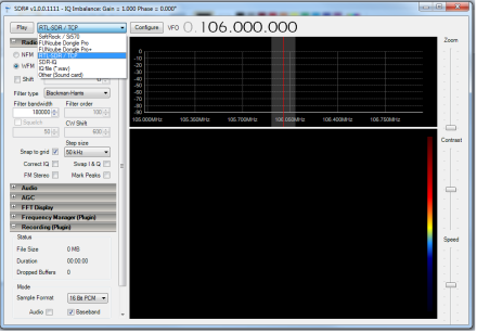
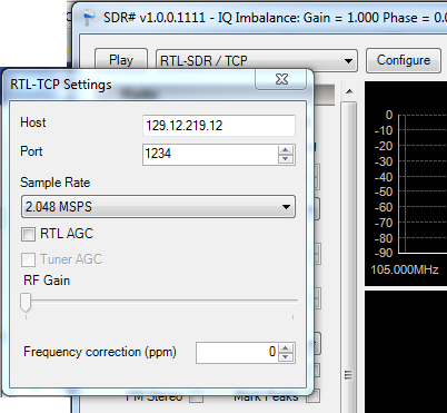
When you have finished configuring, just press play. If all has gone well, then you will see the waterfall of data start to fall down the screen and hopefully hear something.  In all likely hood you won’t hear anything straight away, so you will want to change the frequency, you can do this by clicking on the top or bottom of the numbers representing the frequency at the top pf the screen, or by clicking along the activity bar.

Happy listening.

————– UPDATE ————–

April 2014

So after not using SDR for over a year I have set up my Pi to listen to the airwaves again. This was sparked by a comment below asking for help.
I followed my own walk-through and encountered the same issues as Ryan had encountered.

I managed to resolve these by adding “blacklist dvb_usb_rtl28xxu” to the file
/etc/modprobe.d/raspi-blacklist.conf by entering

sudo nano /etc/modprobe.d/raspi-blacklist.conf 

and entering the extra line at the bottom.

After rebooting everything worked well.

Solving Quadratics

So to start off a new area of discovery I have decided to start to learn Python.

To start off this undertaking I downloaded Python 2.7.3 from python/download and started to play around with IDLE, python’s Integrated DeveLopment Environment (IDE).

As a project to work on to learn this new language I decided to make a simple console application that try’s to calculates the value of X for a given quadratic.  To do this it will use the quadratic formula

Image

So to do this I first need the values of a, b, and c as per the formula.    Image

for example a = 1, b = -9, and c = 20.

The first step logical step was to cut the equation into 3 chunks:

  1. The Discriminant (Δ); b^2 – 4ac
    1. sqrB = pow(b, 2)
      AC = 4*a*c
      Delta = math.sqrt(sqrB – AC)
    2. the “pow(x,y)” function returns the first term to the power of the second, i.e. b^2
    3. the math.sqrt is a function of the math module which square roots the contents of the brackets, or to use the technical name, parentheses.
  2. The Numerator; -b +- √Δ
    1. NumeratorPlus = -b + Delta
      NumeratorMinus = -b – Delta
  3. The Denominator; 2a
    1. Denominator = 2*a

Then with the necessary components the values of X can then be calculated by:

XPlus = NumeratorPlus / Denominator
XMinus = NumeratorMinus / Denominator

and then be outputed on the screen using the print command:

print (“Your answer is, X = “), XPlus, (“Or X = “), XMinus

notice the comma’s after each component which are needed.

And so the final step was to allow the user to enter in values:

print (“Please separate the quadratic equation into aX^2 + bX + C = 0”)
a=input(“Please Enter the Value of a : “)
b=input(“Please Enter the Value of b : “)
c=input(“Please Enter the Value of c : “)

The “input” function is important as it prints the given prompt to the output and then reads in the data entered by the user and assigns it to the variable.

This is different to the “raw_input” function which is not syntax sensitive.

And so the final code looks like:

import math
from time import sleep

print (“Please seperate the quadratic equation into aX^2 + bX + C = 0”)
a=input(“Please Enter the Value of a : “)
b=input(“Please Enter the Value of b : “)
c=input(“Please Enter the Value of c : “)

sqrB = pow(b, 2)
AC = 4*a*c
Delta = math.sqrt(sqrB – AC)
NumeratorPlus = -b + Delta
NumeratorMinus = -b – Delta

Denominator = 2*a
XPlus = NumeratorPlus / Denominator
XMinus = NumeratorMinus / Denominator

print (“Your answer is, X = “), XPlus, (“Or X = “), XMinus

sleep(10)

Image