PlotBot: Building the Machine

With the research all done, I started thinking about how I wanted to build my PlotBot.
Having looked at the other designs, I found they were either mounted on a wooden frame and then a piece of paper is taped onto the wooden panel, or they draw directly onto a surface like glass or a wall. Given that the aim is just to make something that catches peoples eye, rather than making posters or drawings for people, I think the best course of action would be to use a whiteboard. I can get one reasonably cheaply, and the mounting is pretty much already sorted.

the Mountings

The whiteboard and mountings.

Once I had bought a whiteboard (600mm x 450mm) I started lining up the parts I had as to how I would mount them.
I had also bought 2 Pololu 1204 Stepper Motors and an Adafruit Motorshield v2 (AFMSv2). I did have a few concerns with these parts combined together, in that the motors only draw 600mA and the motorshield provides 1.2A per channel, therefore the motors might get a little hot if they start drawing more than they should – but we’ll see how it goes!

rough positioning

Roughly lining up the parts on a sheet of acrylic.

To mount the acrylic sheet to the whiteboard I used two of the mounts supplied with the whiteboard secured on the top of the sheet. These then hook onto the edge of the whiteboard, and the mounts on the side are adjustable to “lock in” the sheet to the sides of the board. Finally I decided to neatly mount the arduino and AFMSv2 in the center of the acrylic sheet.
Drawing up where to cut

Whiteboard Mounting     Arduino Mountings

IMG_20140813_134431     IMG_20140813_110556_1

I picked up two remote control car wheels at a local hobby store, along with 50m of fishing line, which would form the basis for my reels.IMG_20140819_220854

I found some nuts in the garage that fitted the inside of the wheel, and used Araldite (metal glue) to fill the gap around the stepper motor shaft hoping that this wouldn’t go wrong.

IMG_20140819_181748IMG_20140820_180654

IMG_20140820_180634

Araldite’s in, I was a little bit messy dripping it everywhere!

 With the luck of the gods, after leaving it 24 hours to cure I was able to punch the stepper motor shaft out of the nut, leaving a nice shaped hole. The advantage of this method being that I can very easily remove the reels and use the steppers in other projects.  

IMG_20140819_220909

IMG_20140819_221038  IMG_20140819_221322

Now that I have the reels mounted on the steppers, I was able to complete the main build; mounting the steppers onto the acrylic sheet, and winding the fishing line onto the wheels – happy days!

IMG_20140903_141549

IMG_20140903_141638  IMG_20140903_141609


So You’ve got yourself a Lilypad?

So as part of my involvement with TinkerSoc, we now have our new hoodies. These hoodies are designed so that a Lilypad Arduino can be sewn onto it and then components added to it. We will be wearing hoodies that we can literally tinker with.

Lilypad Arduino

For those that don’t know, the Arduino Lilypad is an Arduino development platform intended for clothing and e-textiles. Using conductive thread you can sew tracks and components onto any fabric and then programmed.
The Lilypad doesn’t have a USB plug like an ordinary Arduino Uno. This is because the Lilypad does not have a FTDI Chip (Future Technology Devices International Ltd) unlike the Uno and many other Arduino’s. The FTDI chip converts the USB to serial communication.

LilyPad Programming_bb

So because the Lilypad doesn’t have a USB connection we can use an Arduino Uno instead. To do this we need to remove the ATMega 328p from the Arduino Uno, then break out the header on the Lilypad. As per the diagram above from left to right, the pins connect to Gnd, Gnd, 5v, Rx, Tx and Reset. With these connections made, we can proceed to connect the Uno to a computer, and then start up the Arduino IDE. While in the IDE, make sure you change the board to the correct version of the Lilypad you are using. (If in doubt try to read the number on the Microcontroller on the centre of the board)

Arduino IDE
And with that done you are ready to start programming, I suggest loading up the example blink program first. Enjoy.

Raspbery Jam & SDR

Inspired by a talk on Software Defined Radio (SDR) during a TinkerSoc night, and motivated by the rocketing number of hits the society’s website after their blog post about SDR was featured on Hack-A-Day. I decided to try it out for myself!

SDR works due to the RTL2832 chipset which has a very wide frequency receiver range. This chipset is used in a lot of the USB TV tuners out there, however not all of them. A list has been compiled on the Osmocom.org website where they also have a huge amount of information about SDR.

Having brought myself a USB TV Tuner off Amazon for £14 and free shipping it is clear that this is a really inexpensive way to get into amateur radio.

P1000558

The USB Tuner arrived at my house at university on the day of the fifth Raspberry Pi Jam, it seemed like an ideal opportunity to combine the two interests.

Having learnt a little bit about the different programs available during the talk at TinkerSoc, I decided to use rt-_tcp a lightweight piece of software that has the RTL (Realtek) drivers.

RTL-tcp is a sub program of RTL-sdr which is a command line interface program for controlling the TV tuner. By using RTL-tcp you are setting up a server which you can then connect to and stream the data from the Raspberry Pi to your computer. The benefit of this is that your antenna can be high up outside in the cold, meanwhile you are inside, nice and cosy.

Arriving at the Raspberry Jam I immediately set myself up with a my RPi connected to all the peripherals like the monitor and keyboard, as well as connecting it to my laptop over an Ethernet cable and I bridged the LAN to my wireless connection in order to install the software.

I was fortunate that two gents were very kind as to start helping me, teaching me my way around the command line and explaining the function of programs like aptitude and git.

Referencing a guide on hamradioscience.com I started to set up my RPi with all the software I needed.

To start with I checked that all dependencies were installed. There are programs that RTL-SDR and -TCP will need in order to work correctly. To check and/or install these dependencies I had to use the sudo apt-get install function and then install git, cmake, libusb-1.0-0.dev and build-essential.

sudo apt-get install git 
sudo apt-get install cmake
sudo apt-get install libusb-1.0-0.dev
sudo apt-get install build-essential

The next step was to download RTL-sdr and install the drivers.

git clone git://git.osmocom.org/rtl-sdr.git
cd rtl-sdr/
mkdir build
cd build
cmake ../
make
sudo make install
sudo ldconfig

The final step is to copy the rules file (rtl-sdr.rules) which can be found at /home/pi/rtl-sdr and this file should be copied into etc/udev/rules.d .

P1000557

Once the rules are in place you need to plug in the TV tuner and then you are ready to test that everything is working correctly by using the command rtl_test -t.

rtl_test

If everything is working all right, as it is in the picture above, then it is time to start the server and then set up your listening station.

To start the server type rtl_tcp -a followed by the ip address of your Pi. The ip address can be found by typing ifconfig into the command line, the ip address is the set of 4 numbers in the eth0 section. next to the lable “inet addr”.

SDR Sharp is a program written in C# that claims to be high performance with design in mind. It is also the program I decided to use with rtl-tcp.

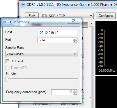
To set SDR Sharp up with the raspberry pi, RTL-SDR / TCP must be selected from the drop down list, and then click configure.

sdrsharp1

The Raspberry Pi’s ip address should be entered into the host cell, and in the Port cell is the default value that doesn’t need to be changed. Volume can be adjusted using the RF Gain slider if you want a more permanent higher volume.

sdrsharp2When you have finished configuring, just press play. If all has gone well, then you will see the waterfall of data start to fall down the screen and hopefully hear something.  In all likely hood you won’t hear anything straight away, so you will want to change the frequency, you can do this by clicking on the top or bottom of the numbers representing the frequency at the top pf the screen, or by clicking along the activity bar.

Happy listening.

————– UPDATE ————–

April 2014

So after not using SDR for over a year I have set up my Pi to listen to the airwaves again. This was sparked by a comment below asking for help.
I followed my own walk-through and encountered the same issues as Ryan had encountered.

I managed to resolve these by adding “blacklist dvb_usb_rtl28xxu” to the file
/etc/modprobe.d/raspi-blacklist.conf by entering

sudo nano /etc/modprobe.d/raspi-blacklist.conf 

and entering the extra line at the bottom.

After rebooting everything worked well.

Prototyping Regulators

Following the mod of the cheap lamp, I had a 12v supply lying around. I figured a good use of it would be to make a supply board for my Raspberry Pi  and other devices I may want to attach to it.

12v AC supply - 2

The supply actually outputs around 13.4 v or so which can be attributed to the tolerances of components used. Regardless of output being greater than 12v, I can still use it with the two different regulators I ordered from Rapid, the L7805cv 5v 1A TO-220 package regulator, and the LM723 adjustable voltage regulator in a 14-DIP package.

7805


LM723

Both regulators have a maximum input voltage of 40v, so the 12v supply will be just fine. However the supply outputs an Alternating Current (AC) signal, this can be converted to Direct Current (DC), which is needed for most general electronics, by passing the supply through a device known as a Bridge Rectifier.

The Bridge Rectifier

Moving On . . .

On my breadboard I first built the circuit to output 5v in order to power my Raspberry Pi. 7805Circuit

This is a standard circuit found in the datasheet however C2 has a value of 100µF and C1 is equal to 10µF.

Oopps . . . Please do remember to put the capacitors the right way round, first time I’ve ever done it, but it turns out these capacitors don’t like 12v going in them the wrong way . . .

P1000519

7805 and Rectifier

So after connecting the capacitors in the right polarity, and attaching a 7W 75Ω power resistor across the regulator’s output to load it, I attached the voltmeter to measure the output.

Near Perfect

Using the 100µF and 10µF combination proved successful and outputted a solid 5.028v, however the datasheet recommends values of 0.33µF and 0.1µF. If anyone understands the reasons for the different values please do comment below because I am very curious as to why they both work.
Additionally I would be interested to know why the AC signal of the 12v supply distorts as seen below when the supply is under load.
Odd wave distortion