PlotBot: Building the Gondola

Next stage of the build is to work out how to hold the pen. Some people call this the gantry or holder, I’ll be calling mine the gondola.
I decided to use lollipop sticks for this, they have a similar length to whiteboard maker pens, reasonably light weight and at only 50p for a pack of 50 sticks and it was an obvious choice!

IMG_20140908_133959

Clamping the Sticks for drilling

Having cut a few sticks down to size I then clamped them together to drill a thread hole through them using my trusty dremel.

IMG_20140908_134639

Lining them up for gluing.

IMG_20140908_135225

First one clamped down.

With the first side clamped in place and the wood glue drying things are starting to take shape.

IMG_20140908_195723

Sides nearly finished.

IMG_20140909_110614

And the finished gondola! look forward to a video of the first test draw in a couple of days . . . things are a bit shaky!

PlotBot: Building the Machine

With the research all done, I started thinking about how I wanted to build my PlotBot.
Having looked at the other designs, I found they were either mounted on a wooden frame and then a piece of paper is taped onto the wooden panel, or they draw directly onto a surface like glass or a wall. Given that the aim is just to make something that catches peoples eye, rather than making posters or drawings for people, I think the best course of action would be to use a whiteboard. I can get one reasonably cheaply, and the mounting is pretty much already sorted.

the Mountings

The whiteboard and mountings.

Once I had bought a whiteboard (600mm x 450mm) I started lining up the parts I had as to how I would mount them.
I had also bought 2 Pololu 1204 Stepper Motors and an Adafruit Motorshield v2 (AFMSv2). I did have a few concerns with these parts combined together, in that the motors only draw 600mA and the motorshield provides 1.2A per channel, therefore the motors might get a little hot if they start drawing more than they should – but we’ll see how it goes!

rough positioning

Roughly lining up the parts on a sheet of acrylic.

To mount the acrylic sheet to the whiteboard I used two of the mounts supplied with the whiteboard secured on the top of the sheet. These then hook onto the edge of the whiteboard, and the mounts on the side are adjustable to “lock in” the sheet to the sides of the board. Finally I decided to neatly mount the arduino and AFMSv2 in the center of the acrylic sheet.
Drawing up where to cut

Whiteboard Mounting     Arduino Mountings

IMG_20140813_134431     IMG_20140813_110556_1

I picked up two remote control car wheels at a local hobby store, along with 50m of fishing line, which would form the basis for my reels.IMG_20140819_220854

I found some nuts in the garage that fitted the inside of the wheel, and used Araldite (metal glue) to fill the gap around the stepper motor shaft hoping that this wouldn’t go wrong.

IMG_20140819_181748IMG_20140820_180654

IMG_20140820_180634

Araldite’s in, I was a little bit messy dripping it everywhere!

 With the luck of the gods, after leaving it 24 hours to cure I was able to punch the stepper motor shaft out of the nut, leaving a nice shaped hole. The advantage of this method being that I can very easily remove the reels and use the steppers in other projects.  

IMG_20140819_220909

IMG_20140819_221038  IMG_20140819_221322

Now that I have the reels mounted on the steppers, I was able to complete the main build; mounting the steppers onto the acrylic sheet, and winding the fishing line onto the wheels – happy days!

IMG_20140903_141549

IMG_20140903_141638  IMG_20140903_141609


PlotBot: Brief

So as time draws on we are getting closer to the start of the new academic year, and of course that means Fresher’s Fair!
At Kent we have several creative societies including SpaceSoc and their “Build a Rocket” sessions, Engineering Soc  with their focus on robotics, and TinkerSoc who want to help people build without limits.
With TinkerSoc it has become somewhat of a tradition to build and showoff a project at the fresher’s fair. In previous years we have had a laser engraver making custom name tags and furbies singing bohemian rhapsody, basically something to grab peoples attention and imagination.
Having seen a number of vertical plotters online I have decided now is the time to build one.

The standard vertical plotter is made up of 2 stepper motors, a servo, a motor controller and a microcontroller. By providing a stream of polar coordinates to the robot, the two motors can be wound in and out to move a pen across the whiteboard. This produces drawings where the pen never leaves the surface however that does not limit the styles of drawings that can be produced. Drawings can be developed further by adding a server or linear actuator to the pen carriage in order to push the pen off the drawing surface, thus allowing mush more freedom to implement different drawing styles.

Obviously we cannot draw above, or on either side of the motors, however the effectiveness of the plotter changes depending on the position of the pen carriage.
As such the most effective drawing area is a rectangle in the centre of the drawing surface with the tension on a cord being too low on either side, and the resolution is too low at the top due to the large angles. (http://2e5.com/plotter/V/design/

image


There have been a great many vertical plotters in the past, a great list can be found at plotterbot.com.
Overall there seem to be two different styles of drawing with vertical plotters.

Single line, where the pen never leaves the surface, is technically less challenging and can provide great results however you can be left with the odd scrawl across the surface that you didn’t want.

Multi line, where the pen can be lifted/pushed away from the surface, allows much more flexibility with regards to what can be drawn as the robot won’t scrawl connecting lines across the surface however does add the extra complexity of having a servo or linear actuator to push the pen carriage away from the surface.

Bearing in mind the saying, the more complex it is, the more likely it is to break.


Tinkerlog’s “Der Krizler” is definitely one of the more popular V-plotters out there, drawing on glass to amuse passers-by.

https://www.flickr.com/photos/8123185@N02/8181763825/


Dan Royer’s Makelangelo is a very impressive V-plotter. Commercialised as a kit, it’s reliability has been tested extensively!

Makelangelo 2.5


And probably the oldest V-plotter around from 1988 developed at MIT using lego!


RC On a Budget

And by budget, I mean cheap and cheerful. Most people that are into the hobby will tell you it can’t be done cheep, well not as cheap as we’re talking. They’ll tell you that at these prices all you can get yourself are kids toys, but what’s wrong with kids toys? It doesn’t stop them from counting as RC models does it? I go from flying my hundreds, if not thousands of pounds worth or model planes and heli’s to chucking one of these £60 machines around the air and honestly, most of the time I have more fun messing around with the little machines. But what are these mystery machines? There are two that I’m going to write about today. The Parkzone Mini Vapor, and the Hubsan X4. Lets start with the Vapor. Image This little beast will set you back a mere £60. And that’s with everything, model, transmitter, battery and charger! And believe me, it’s worth every penny!   After spending a whole day flying both the Vapor and the Hubsan around in my gliding club hanger, aswell as the clubhouse I can confidently tell you this docile little machine really is brilliant. It flies around almost silently, and very slowly. Performing gradual sweeping turns or tight spirals. Altitude adjustments are easy as it has plenty of power and elevator control. and best of all, it’s really easy to fly! Perfect for someone who has never flown before.   Out of the box all you have to do is insert the batteries into the included controller and battery charger, then charge the flight battery which only takes half an hour or so and gives you nearly 10 mins of flight time! Once the battery is charged its very simple to plug-in, and affix to the bottom of the model using Velcro. Now you’re ready to take to the skies! Half throttle will get you easily off the ground or any reasonably sized table, and this thing will just potter around gracefully. Landings just as easy too as its impossible to get this thing to stall. Now the Hubsan X4! Hubsan X4   Wow, Just Wow! I’m used to flying Quads around that are 10 times the size, and more than 10 times the cost and this thing is just better! Yes its only a “toy”, and no it can’t carry a big fancy camera and any of that stuff, but I just want one! And I want all of my friends to get one too so we can all go fly these around. Now Quadrocopters are usually rather tricky to fly, one of the main issues being the orientation of the aircraft, but these things are easy, so easy. You do of course still get the orientation problems, but all you have to do is spin the thing back round, or let go of the sticks entirely as this things on board brain is fantastic. It keeps the thing dead level, even in a rather stong breeze (of course we had to test it in more than “a breeze” and it coped amazingly well). Almost anyone can pick up the controls for the Hubsan in almost any sized space and be flying one of these around like a pro. It has 3 built-in flight modes, beginner, advanced and aerobatic. Yes you read that right, this thing will do flips! For a measly £30 you get the model, a battery, the controller and a USB battery charger. Additional batteries are easily available for a very low-cost as well as other spare parts for when you eventually break a propeller, which is nice.   I can do nothing but praise these two models, and i think anyone would be happy with either of them, or both! perfect for beginners and the wizened pros alike, these just give you a break from the hustle and bustle to just mess around with a few toys again. Now to stop boring you with words and show you a few photos! IMG_6545 IMG_6572      IMG_6808 IMG_6805

Glass Circuits

So one day I was bored and had a few things lying around:

  1.  Copper tape
  2. A pane of glass from a scanner
  3. 555 timer & passives
  4. soldering iron

There was really only one logical thing to do to assist in my procrastination, put together an astable 555 circuit on the glass!

P1010637_1Through my time learning about electronics, I have come to realise that the 555 timer circuit, astable or monostable, is one of the first circuits anyone should make.

However for those who don’t know about it here is a short explanation of the astable circuit.555astable

The 555 timer IC is a a circuit of over 40 components, including 25 transistors and 15 resistors, all printed on a silicone chip.

The circuit works by flipping the voltage states of different pins on the IC. Initially pin 7 is high and so the current flows though R1 & R2 to charge the capacitor. Pin 6 detects the high voltage build up on the capacitor and toggles pin 7 to be pulled low, this causes the capacitor to discharge through R2. While the capacitor is discharging, pin 3 is pulled low, turning off the output, however when pin 2 detects the low voltage on the capacitor, pin 7 is pulled high again, allowing the current to flow through R1 & R2 again.

555 Astable GIF

And ofcourse there is some maths to work out the length of each high and low pulse for given component values, and thus the frequency as well.

f = 1 / ( ln(2) * C * ( R1 + 2R2 ) )

High = ln(2) * C * ( R1 + R2 )

Low = ln(2) * C * R2

And so with values of 1000Ω for R1 and 10KΩ for R2, and 100μF for C1, we get a high pulse of 0.76 seconds, and a low pulse of 0.69 seconds and a frequency of 0.69Hz (687 mHz).

P1010632

P1010634


testing timer

Having a go at Book Binding

For some time I have wanted to have a go at book binding. It seems like a great thing to do as a gift for a loved one, but maybe that’s just me. Well I decided to make my girlfriend a photo album and sketch book as a Christmas present. Hence why this is being published after Christmas to avoid her surprise being ruined. On the next occasion that I decide to make a book I would choose paper with a lower gsm that I have done for these. I selected 300 gsm, which is great for the photo album, however for the book it is a little too thick to easily flick the pages.

Anyway, to the book binding process. After having folded 20 sheets of paper I clamped them together in-between two other books (sheets of wood are better) and then coated the folded edges with Copydex, a latex based contact adhesive, and a cut of cloth placed over it. By doing this the Copydex soaks into the cloth and the paper to make a reasonably strong joint.

wpid-IMG_20131213_035455.jpg

Now that the pages have been bound, its time to make the cover. Using 5mm rigid foam and sticky back cloth, I cut out the front, back and the spine and laid the parts out on the cloth. When doing this make sure to leave a large border of cloth which is used in the next step to cover the edges.

wpid-IMG_20131223_150137.jpg

Alas I forgot to take enough photos but the next step is to fold the edges of the cloth up and over to cover the edges of the board. this can be a little tricky because of the sticky-ness but it looks good if you persevere.

wpid-IMG_20131223_184518.jpg

In order to securely join the pages and the cover, we have to use a joining page which gets glued on the front and back cover, and the front and back of the stack of pages. Finally we are starting to look a bit more professional and are ready to glue in the pages.

wpid-IMG_20131223_184543.jpg

wpid-IMG_20131223_184610.jpg

wpid-IMG_20131223_184532.jpg

Make sure to use a nice big weight when gluing in the pages just to make sure everything is nice and flat!

wpid-IMG_20131224_123026.jpg

wpid-IMG_20131224_123033.jpg

No photo’s of the finished book. Sad times.

Hameg 203-4

As usual you can find some great bargains on eBay!

A few weeks ago I brought my first oscilloscope, a Hameg HM203-4, on eBay for £14.51, quite a deal I think. It was sold as “For parts or not working” as the seller didn’t know anything about oscilloscopes  or how to use them.

The Hameg HM203-4

The Hameg HM203-4

P1010452

I do love that there is a warning about the X Ray dosage!

Although it was sold on eBay as good condition, one of the buttons was missing. Fortunately I was able to see it inside the casing and so wasn’t too worried.

P1010457

So its time to crack it open and see what’s inside . . . Just two screws on the back and the whole metal chassis slides off.

P1010453

just two screws on the back

With the metal chassis removed we get our first glimpse into the home of the magic smoke. Just as I had hoped the missing switch was just a case of the shaft having popped out of the holder, I wonder what happened. . .

P1010456

P1010459

P1010461

A nice easy fix =]

So now that is fixes, here are some specs. Its a dual channel scope with a bandwidth of 20 MHz its not the fastest beast out there but then its not the slowest either, backed up by a max input sensitivity of 2mV/cm. One feature I’m interested to try and think might be pretty good for me as a student is the component tester. to make matters even better its apparently recommended for the training of engineers, perfect.

P1010462

What a pretty board

P1010463

P1010470

Poles Poles Poles, and a little bodge 🙂

P1010466

I was amazed to find capacitors without venting on the top!

P1010474

At least the CRT was made in 1983.

In the Aftermath of the Mini Maker Faire

The dust is settling now after the hordes of people who wandered through the halls of the Elephant & Castle Mini Maker Faire.

Within the halls of the London College of Communication, makers were separated by categories into different studios. We had lots to look at and admire, however Raspberry Pi’s and 3D printers, not surprisingly took centre stage.

I don’t intend to talk about everything that happened, just a few things that really made an impression on me.

One 3D printer that caused me to take a second glance, and a third, and a fourth, and a chat with the creator, was the 3DR.
The 3DR is an inverted delta-bot style 3D printer that is constructed mainly out of 3D printed parts. Because of the simple design it seems to me that it must be must easier to set-up initially as the only areas you need to focus on are how tight the strings/cam belt are, and the position of the 3 arms, of course that is only the case if the rod guides are all the same height and parallel to each other.

A 3D printing company caught my eye as we wandered around because of their impressive printed objects and nicely build RepRap printers. Active 3D is based in Tunbridge Wells and aim to help introduce schools in the area to the opportunities that are available in 3D Printing. They offer workshops and monthly meetups which aim:

  • To train people in how to use 3D printers.
  • To train people how to maintain a 3D printer.
  • To provide an easy to use instruction manual.

And finally, catering to the more artistic of us, and the thirsty, the Tropism Well could be found in one of the main halls.
The Tropism Well is a drinking fountain with a difference. With a base made up of a 14 litre tank, which can be filled with any beverage, the Well automatically detects the presence  of a person and elegantly bow’s its neck, presenting to the honoured person a gift of a perfectly poured serving or a drink, before bringing its neck back up straight as if to observe you enjoying its gift.

Elephant & Castle Mini Maker Faire


Elephant & Castle Mini Maker Faire

So the three of us are off to The Elephant & Castle Mini Maker Faire on Saturday.
Maker Faire’s were created by Make Magazine in the USA, they are now events that happen all over the world.

Currently in the UK we have 6 Mini Maker Faire’s in; Brighton, London, Nottingham, Manchester, Dublin and Edinburgh. There is also a “featured” Maker Faire in Newcastle. Find your nearest Maker Faire here.

On the agenda for the Elephant & Castle Mini Maker Faire in London are loads of workshops including learning to solder (Through Hole and Surface mount),  creating a mini synth and 3D modelling in Blender. See the full list here.

We are really looking forward to the day and will update everyone with what we see and do! =]

919810_10201066545723286_449519429_o


Twitter LED (Broken/Being repaired)

Note: Before you start this article take note that the LED lighting code and word recognition should still work but twitter have made it so you can’t access tweets this way anymore. You have to sign up to be a developer and insert authentication code. I am trying to currently repair this but twitter aren’t making it easy 😛

For future projects and general usefulness I have decided to try to learn a new programming language. I have decided to try python for two good reasons, because it is a good language to program projects with the Raspberry Pi and because a large chunk of my course next year is programming simulations in python.

For my first program I’m going to do a twitter feed controlled LED, I also plan to incorporate twitter into a later project so this is a good starting point.

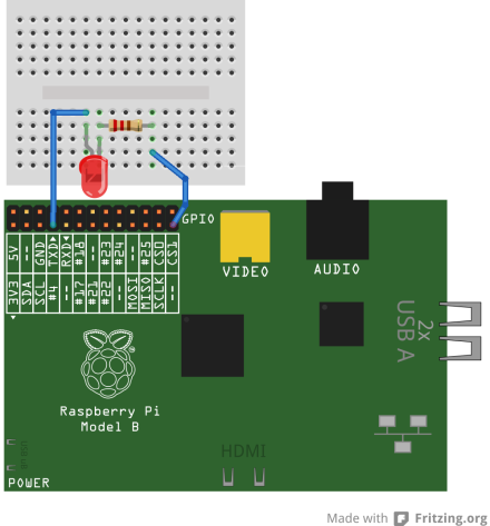
Ingredients list: A Raspberry Pi, an LED, a 220 Ohm resistor, Internet access and a Twitter account.

First take an LED and a 220 Ohm resistor and connect the resistor to the cathode of the LED. Then connect the anode of the LED to pin 7 of the GPIO pins on the Raspberry Pi and the resistor to pin 25 using two female to female jumper wires. A GPIO pin layout diagram can be found here. Once you are sure this is done correctly, a mistake could damage the Pi, boot up your Raspberry Pi ( I am using Raspbian Wheezy). This is all the hardware setup.

prLED

Now to install the appropriate libraries type this into the command line:

wget https://raw.github.com/Rob-Bishop/RaspberryPiRecipes/master/InstallTweetLEDLibraries.sh

Now run the installer by typing sudo: sh InstallTweetLEDLibraries.sh

Okay you know have the appropriate library the next step is to create the file. I’m using nano, to make he file type this command:

nano TweetLED.py

In the editor you just opened type the following code, quick tip press CTRL X to save and exit the editor. Note, I am going to put ; at the end of each line to make the program clearer do not put these into your program.

import urllib ;

import simplejson ;

import time ;

import RPi.GPIO as GPIO ;

;

GPIO.cleanup() ;

GPIO.setmode(GPIO.BOARD) ;

GPIO.setup(7,GPIO.OUT) ;

;

def latest_tweet(twitter_handle): ;

twitter_results = urllib.urlopen(‘http://’+’search.twitter.com/search.json?q=’+twitter_handle) ;

result_list = simplejson.loads(twitter_results.read()) ;

return result_list[‘results’][0][‘text’] ;

;

count = 1 ;

;

while count > 0: ;

tweet=latest_tweet(‘@JamesLeftley’) ;

;

if ‘on’ in tweet: ;

print tweet,’ – LED ON’,’\n’ ;

GPIO.output(7,GPIO.HIGH) ;

;

if ‘off’ in tweet: ;

print tweet,’ – LED OFF’,’\n’ ;

GPIO.output(7,GPIO.LOW) ;

;

if ‘stop’ in tweet: ;

print tweet,’ – Stopped’,’\n’ ;

GPIO.output(7,GPIO.LOW) ;

count = 0 ;

;

time.sleep(2) ;

Now save and exit using CTRL X and you should be taken back to the command line. To run the program type:

sudo python TweetLED.py

To stop the program tweet stop, to turn the LED on tweet on and to turn the LED off tweet off. The tweets can say anything as long as they include the twitter handle, in this case @JamesLeftley, and the command. All the commands are case sensitive.

To personalise the program change the twitter handle, add more outputs and change the commands.