Next stage of the build is to work out how to hold the pen. Some people call this the gantry or holder, I’ll be calling mine the gondola.
I decided to use lollipop sticks for this, they have a similar length to whiteboard maker pens, reasonably light weight and at only 50p for a pack of 50 sticks and it was an obvious choice!
Clamping the Sticks for drilling
Having cut a few sticks down to size I then clamped them together to drill a thread hole through them using my trusty dremel.
Lining them up for gluing.
First one clamped down.
With the first side clamped in place and the wood glue drying things are starting to take shape.
Sides nearly finished.
And the finished gondola! look forward to a video of the first test draw in a couple of days . . . things are a bit shaky!
With the research all done, I started thinking about how I wanted to build my PlotBot. Having looked at the other designs, I found they were either mounted on a wooden frame and then a piece of paper is taped onto the wooden panel, or they draw directly onto a surface like glass or a wall. Given that the aim is just to make something that catches peoples eye, rather than making posters or drawings for people, I think the best course of action would be to use a whiteboard. I can get one reasonably cheaply, and the mounting is pretty much already sorted.
The whiteboard and mountings.
Once I had bought a whiteboard (600mm x 450mm) I started lining up the parts I had as to how I would mount them. I had also bought 2 Pololu 1204 Stepper Motors and an Adafruit Motorshield v2 (AFMSv2). I did have a few concerns with these parts combined together, in that the motors only draw 600mA and the motorshield provides 1.2A per channel, therefore the motors might get a little hot if they start drawing more than they should – but we’ll see how it goes!
Roughly lining up the parts on a sheet of acrylic.
To mount the acrylic sheet to the whiteboard I used two of the mounts supplied with the whiteboard secured on the top of the sheet. These then hook onto the edge of the whiteboard, and the mounts on the side are adjustable to “lock in” the sheet to the sides of the board. Finally I decided to neatly mount the arduino and AFMSv2 in the center of the acrylic sheet.
I picked up two remote control car wheels at a local hobby store, along with 50m of fishing line, which would form the basis for my reels.
I found some nuts in the garage that fitted the inside of the wheel, and used Araldite (metal glue) to fill the gap around the stepper motor shaft hoping that this wouldn’t go wrong.
Araldite’s in, I was a little bit messy dripping it everywhere!
With the luck of the gods, after leaving it 24 hours to cure I was able to punch the stepper motor shaft out of the nut, leaving a nice shaped hole. The advantage of this method being that I can very easily remove the reels and use the steppers in other projects.
Now that I have the reels mounted on the steppers, I was able to complete the main build; mounting the steppers onto the acrylic sheet, and winding the fishing line onto the wheels – happy days!
So as time draws on we are getting closer to the start of the new academic year, and of course that means Fresher’s Fair! At Kent we have several creative societies including SpaceSoc and their “Build a Rocket” sessions, Engineering Soc with their focus on robotics, and TinkerSoc who want to help people build without limits. With TinkerSoc it has become somewhat of a tradition to build and showoff a project at the fresher’s fair. In previous years we have had a laser engraver making custom name tags and furbies singing bohemian rhapsody, basically something to grab peoples attention and imagination. Having seen a number of vertical plotters online I have decided now is the time to build one.
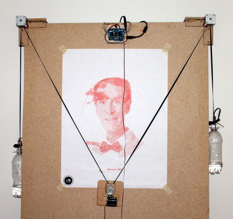
The standard vertical plotter is made up of 2 stepper motors, a servo, a motor controller and a microcontroller. By providing a stream of polar coordinates to the robot, the two motors can be wound in and out to move a pen across the whiteboard. This produces drawings where the pen never leaves the surface however that does not limit the styles of drawings that can be produced. Drawings can be developed further by adding a server or linear actuator to the pen carriage in order to push the pen off the drawing surface, thus allowing mush more freedom to implement different drawing styles.
Obviously we cannot draw above, or on either side of the motors, however the effectiveness of the plotter changes depending on the position of the pen carriage. As such the most effective drawing area is a rectangle in the centre of the drawing surface with the tension on a cord being too low on either side, and the resolution is too low at the top due to the large angles. (http://2e5.com/plotter/V/design/
There have been a great many vertical plotters in the past, a great list can be found at plotterbot.com. Overall there seem to be two different styles of drawing with vertical plotters.
Single line, where the pen never leaves the surface, is technically less challenging and can provide great results however you can be left with the odd scrawl across the surface that you didn’t want.
Multi line, where the pen can be lifted/pushed away from the surface, allows much more flexibility with regards to what can be drawn as the robot won’t scrawl connecting lines across the surface however does add the extra complexity of having a servo or linear actuator to push the pen carriage away from the surface.
Bearing in mind the saying, the more complex it is, the more likely it is to break.
Tinkerlog’s “Der Krizler” is definitely one of the more popular V-plotters out there, drawing on glass to amuse passers-by.
So the three of us are off to The Elephant & Castle Mini Maker Faire on Saturday. Maker Faire’s were created by Make Magazine in the USA, they are now events that happen all over the world.
Currently in the UK we have 6 Mini Maker Faire’s in; Brighton, London, Nottingham, Manchester, Dublin and Edinburgh. There is also a “featured” Maker Faire in Newcastle. Find your nearest Maker Faire here.
On the agenda for the Elephant & Castle Mini Maker Faire in London are loads of workshops including learning to solder (Through Hole and Surface mount), creating a mini synth and 3D modelling in Blender. See the full list here.
We are really looking forward to the day and will update everyone with what we see and do! =]
Tonight was my first time along at the London Arduino Meet Up.
The London Arduino Group is of a similar idea to the Raspberry Pi Jam events that I’ve been to
before. It is a group of people who want to share knowledge about the Arduino platform and start to
innovate across other platforms.
This month we had presentations including hobby electronics, internet controlled LED’s and 3D
printing.
Using an Ethernet shield, Christian, put together a set up where he was able to control the status
of an LED in his web browser. This was done on a local network (sorry guys who wanted to take
control of his little light) where he showed two methods of flicking the switch.
The first method he showed off was to use the arduino as a web server and construct the html on it
as well. Then it was a simple matter of connecting to the IP address that was defined on the
arduino and hey-presto it worked.
The second method that he demonstrated was a little more complicated involving node.JS, sockets and other technical jargon that I didn’t catch.
On a similar vein we had Liam demonstrating the use of a TP-Link Wireless N Nano Router (TL-WR702N) to connect an arduino to the internet. He argued that the use of WiFi shields is overly complicated compared to Ethernet shields, as well as being a lot more expensive So if you are willing to have a slightly bigger package then you can connect the Ethernet shield to the nano router and leave that to sort out the complicated subtleties of wireless connections, allowing you to get on with innovating your wireless solution. Another thought is that a nano router is much more versatile than a WiFi shield because it can be plugged into a computer, games console, Raspberry Pi, or any other device that has an Ethernet socket.
In the realm of Hobby Electronics we had Danny, who was plugging his first ever kit robot. Orionrobots.co.uk is his creation and is where he is selling his first his own starter kit robot. In this kit you will find everything that you need to to construct a small chassis with 4 wheels controlled in pairs (left and right) by a L298n dual H-Bridge controller board which is interfaced to an Arduino Uno R3 (provided in the kit). With a easy fit design, you only need a screwdriver to put this kit together making it perfect for anyone who is; unsure with tools, in need for a robot chassis quickly, or just lazy.
The final talk of the evening was from Mark, on behalf of another London Tech Meet-up group, Future Manufacturing, who have a keen interest in 3D printing. They are really keen to see cross collaboration between our two groups on various projects including potentially the Luma Module Interactive Spaceship. The Luma Module is a KickStarter project where they want to build a spaceship that lights up when people interacts with it. This spaceship will then be shipped (no it won’t fly itself) to Nevada for the Burning Man art Festival at the end of August 2013.
So as part of my involvement with TinkerSoc, we now have our new hoodies. These hoodies are designed so that a Lilypad Arduino can be sewn onto it and then components added to it. We will be wearing hoodies that we can literally tinker with.
For those that don’t know, the Arduino Lilypad is an Arduino development platform intended for clothing and e-textiles. Using conductive thread you can sew tracks and components onto any fabric and then programmed.
The Lilypad doesn’t have a USB plug like an ordinary Arduino Uno. This is because the Lilypad does not have a FTDI Chip (Future Technology Devices International Ltd) unlike the Uno and many other Arduino’s. The FTDI chip converts the USB to serial communication.
So because the Lilypad doesn’t have a USB connection we can use an Arduino Uno instead. To do this we need to remove the ATMega 328p from the Arduino Uno, then break out the header on the Lilypad. As per the diagram above from left to right, the pins connect to Gnd, Gnd, 5v, Rx, Tx and Reset. With these connections made, we can proceed to connect the Uno to a computer, and then start up the Arduino IDE. While in the IDE, make sure you change the board to the correct version of the Lilypad you are using. (If in doubt try to read the number on the Microcontroller on the centre of the board)
And with that done you are ready to start programming, I suggest loading up the example blink program first. Enjoy.
To keep myself busy at university, I decided to start on a big project. Well big for me anyway.
The end goad being a a VU (Volume Unit) meter, aka a sound level, that can be used either in-line with an audio cable, or used with a microphone.
I am to try to go through this project in a number of research stages, and main 3 test stages.
For the research I want to start with a Light Level Meter. This will just help me to refresh my arduino programming skills, and also just set myself up for when I get hold of a microphone.
Next I will take the same circuit and apply it to audio, using a microphone and using a line-in. In terms of analysing the audio I will first try using a simple analogRead, just the same as the Light Level Meter. I will also look into using FFT (fast Fourier transform) which is used to transform raw audio into a frequency spectrum, which in turn can be outputted to LED displays. This route could end up being very complicated so I will approach that with caution.
The next stage is to research multiplexing and charlieplexing LED’s. This is because I would like the end product to have a LED matrix display, thus enabling me to potentially display a spectrum of frequency bands. However for the testing I will move back to the Light Level Meter and try to display that data on the LED display.
In terms of the test stages, I will be doing all initial research on breadboards, if all goes to well I will move onto designing an arduino shield, the hope is that this will also work as a Lol (Lots of Lights) Shield. Finally I want to take this to an end product, on its own PCB.
~~~~~~~~~~~~~~~~~~~~~~~~~~~~~~~~~~~~~~~~
So enough talking, time to refresh on the very basics.
The Light Level Meter.
This is a very simple circuit, but then that was not the purpose of it.
Each LED was connected to a pin on the arduino, and the central pin of a variable potentiometer is connected to an analogue in pin. I connected an LDR (Light Dependant Resistor) between the variable pot and 5v. The other pin of the variable pot is pulled down to 0v.
Light Level Vs Resistance over a LDR
As the light level decreases, the resistance over the LDR increases, combining this in a basic potential divider circuit means that as it gets darker, the value read in at the analogue pin of the arduino gets higher. This allows me to adjust the LED’s appropriately and also use the variable pot to calibrate the display.
The circuit seen below is the circuit used, with a 330 Ohm resistor in series with every LED as a current limiting resistor.
To program the arduino I used the standard arduino IDE, available from arduino.cc, and I programmed the arduino with the below sketch.
// LED Light Level Meter
int led[10] = {3, 4, 5, 6, 7, 8, 9, 10, 11, 12}; // Array of pin numbers for the LED’s int adjust = 5; // Adjustment Pot int Light, i;
void setup() { for (i=0;i<10; i++) // A for loop which goes from 0 to 9, setting pinMode(led[i], OUTPUT); // each value in the array as an output Serial.begin(9600); // Turning on the serial output to troubleshoot }
void loop() { Light = analogRead(adjust); // Reading the analogue value of the LDR Serial.println(Light); // sending the value to the computer for troubleshooting Light = Light / 100; //reducing the value down to between 0 and 10 Serial.println(Light); // sending the value to the computer again
if (Light == 0) // checking that all LED’s are off if there is no light { for(i = 0; i < 10; i++) { digitalWrite(led[i], LOW); } }
else { for(i = 0; i < Light; i++) // Turns on all LED’s between 0 and the light level { digitalWrite(led[i], HIGH); }
for(i = i; i < 10; i++) // turn off the leds above the light level { digitalWrite(led[i], LOW); } } delay(100);
So to start off a new area of discovery I have decided to start to learn Python.
To start off this undertaking I downloaded Python 2.7.3 from python/download and started to play around with IDLE, python’s Integrated DeveLopment Environment (IDE).
As a project to work on to learn this new language I decided to make a simple console application that try’s to calculates the value of X for a given quadratic. To do this it will use the quadratic formula
So to do this I first need the values of a, b, and c as per the formula.
for example a = 1, b = -9, and c = 20.
The first step logical step was to cut the equation into 3 chunks:
and then be outputed on the screen using the print command:
print (“Your answer is, X = “), XPlus, (“Or X = “), XMinus
notice the comma’s after each component which are needed.
And so the final step was to allow the user to enter in values:
print (“Please separate the quadratic equation into aX^2 + bX + C = 0”) a=input(“Please Enter the Value of a : “) b=input(“Please Enter the Value of b : “) c=input(“Please Enter the Value of c : “)
The “input” function is important as it prints the given prompt to the output and then reads in the data entered by the user and assigns it to the variable.
This is different to the “raw_input” function which is not syntax sensitive.
And so the final code looks like:
import math from time import sleep
print (“Please seperate the quadratic equation into aX^2 + bX + C = 0”) a=input(“Please Enter the Value of a : “) b=input(“Please Enter the Value of b : “) c=input(“Please Enter the Value of c : “)