So the three of us are off to The Elephant & Castle Mini Maker Faire on Saturday. Maker Faire’s were created by Make Magazine in the USA, they are now events that happen all over the world.
Currently in the UK we have 6 Mini Maker Faire’s in; Brighton, London, Nottingham, Manchester, Dublin and Edinburgh. There is also a “featured” Maker Faire in Newcastle. Find your nearest Maker Faire here.
On the agenda for the Elephant & Castle Mini Maker Faire in London are loads of workshops including learning to solder (Through Hole and Surface mount), creating a mini synth and 3D modelling in Blender. See the full list here.
We are really looking forward to the day and will update everyone with what we see and do! =]
Tonight was my first time along at the London Arduino Meet Up.
The London Arduino Group is of a similar idea to the Raspberry Pi Jam events that I’ve been to
before. It is a group of people who want to share knowledge about the Arduino platform and start to
innovate across other platforms.
This month we had presentations including hobby electronics, internet controlled LED’s and 3D
printing.
Using an Ethernet shield, Christian, put together a set up where he was able to control the status
of an LED in his web browser. This was done on a local network (sorry guys who wanted to take
control of his little light) where he showed two methods of flicking the switch.
The first method he showed off was to use the arduino as a web server and construct the html on it
as well. Then it was a simple matter of connecting to the IP address that was defined on the
arduino and hey-presto it worked.
The second method that he demonstrated was a little more complicated involving node.JS, sockets and other technical jargon that I didn’t catch.
On a similar vein we had Liam demonstrating the use of a TP-Link Wireless N Nano Router (TL-WR702N) to connect an arduino to the internet. He argued that the use of WiFi shields is overly complicated compared to Ethernet shields, as well as being a lot more expensive So if you are willing to have a slightly bigger package then you can connect the Ethernet shield to the nano router and leave that to sort out the complicated subtleties of wireless connections, allowing you to get on with innovating your wireless solution. Another thought is that a nano router is much more versatile than a WiFi shield because it can be plugged into a computer, games console, Raspberry Pi, or any other device that has an Ethernet socket.
In the realm of Hobby Electronics we had Danny, who was plugging his first ever kit robot. Orionrobots.co.uk is his creation and is where he is selling his first his own starter kit robot. In this kit you will find everything that you need to to construct a small chassis with 4 wheels controlled in pairs (left and right) by a L298n dual H-Bridge controller board which is interfaced to an Arduino Uno R3 (provided in the kit). With a easy fit design, you only need a screwdriver to put this kit together making it perfect for anyone who is; unsure with tools, in need for a robot chassis quickly, or just lazy.
The final talk of the evening was from Mark, on behalf of another London Tech Meet-up group, Future Manufacturing, who have a keen interest in 3D printing. They are really keen to see cross collaboration between our two groups on various projects including potentially the Luma Module Interactive Spaceship. The Luma Module is a KickStarter project where they want to build a spaceship that lights up when people interacts with it. This spaceship will then be shipped (no it won’t fly itself) to Nevada for the Burning Man art Festival at the end of August 2013.
So as part of my involvement with TinkerSoc, we now have our new hoodies. These hoodies are designed so that a Lilypad Arduino can be sewn onto it and then components added to it. We will be wearing hoodies that we can literally tinker with.
For those that don’t know, the Arduino Lilypad is an Arduino development platform intended for clothing and e-textiles. Using conductive thread you can sew tracks and components onto any fabric and then programmed.
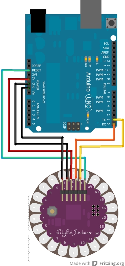
The Lilypad doesn’t have a USB plug like an ordinary Arduino Uno. This is because the Lilypad does not have a FTDI Chip (Future Technology Devices International Ltd) unlike the Uno and many other Arduino’s. The FTDI chip converts the USB to serial communication.
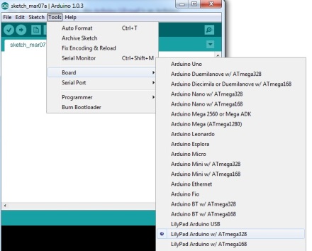
So because the Lilypad doesn’t have a USB connection we can use an Arduino Uno instead. To do this we need to remove the ATMega 328p from the Arduino Uno, then break out the header on the Lilypad. As per the diagram above from left to right, the pins connect to Gnd, Gnd, 5v, Rx, Tx and Reset. With these connections made, we can proceed to connect the Uno to a computer, and then start up the Arduino IDE. While in the IDE, make sure you change the board to the correct version of the Lilypad you are using. (If in doubt try to read the number on the Microcontroller on the centre of the board)
And with that done you are ready to start programming, I suggest loading up the example blink program first. Enjoy.
I would like to thank all those who have looked around this website over the past few months, and a especially big thanks to those who have commented and given advice.
I am pleased to announce that it is no longer just me running this blog as Bradley joins the team. He has a keen interested in electronics, aviation, and photography so I am sure that we will see some cool projects and posts from him.
If anyone does have any advice or comments they would like to share, please do leave them down below or send us an email at theelectronicbyte@gmail.com
To keep myself busy at university, I decided to start on a big project. Well big for me anyway.
The end goad being a a VU (Volume Unit) meter, aka a sound level, that can be used either in-line with an audio cable, or used with a microphone.
I am to try to go through this project in a number of research stages, and main 3 test stages.
For the research I want to start with a Light Level Meter. This will just help me to refresh my arduino programming skills, and also just set myself up for when I get hold of a microphone.
Next I will take the same circuit and apply it to audio, using a microphone and using a line-in. In terms of analysing the audio I will first try using a simple analogRead, just the same as the Light Level Meter. I will also look into using FFT (fast Fourier transform) which is used to transform raw audio into a frequency spectrum, which in turn can be outputted to LED displays. This route could end up being very complicated so I will approach that with caution.
The next stage is to research multiplexing and charlieplexing LED’s. This is because I would like the end product to have a LED matrix display, thus enabling me to potentially display a spectrum of frequency bands. However for the testing I will move back to the Light Level Meter and try to display that data on the LED display.
In terms of the test stages, I will be doing all initial research on breadboards, if all goes to well I will move onto designing an arduino shield, the hope is that this will also work as a Lol (Lots of Lights) Shield. Finally I want to take this to an end product, on its own PCB.
~~~~~~~~~~~~~~~~~~~~~~~~~~~~~~~~~~~~~~~~
So enough talking, time to refresh on the very basics.
The Light Level Meter.
This is a very simple circuit, but then that was not the purpose of it.
Each LED was connected to a pin on the arduino, and the central pin of a variable potentiometer is connected to an analogue in pin. I connected an LDR (Light Dependant Resistor) between the variable pot and 5v. The other pin of the variable pot is pulled down to 0v.
Light Level Vs Resistance over a LDR
As the light level decreases, the resistance over the LDR increases, combining this in a basic potential divider circuit means that as it gets darker, the value read in at the analogue pin of the arduino gets higher. This allows me to adjust the LED’s appropriately and also use the variable pot to calibrate the display.
The circuit seen below is the circuit used, with a 330 Ohm resistor in series with every LED as a current limiting resistor.
To program the arduino I used the standard arduino IDE, available from arduino.cc, and I programmed the arduino with the below sketch.
// LED Light Level Meter
int led[10] = {3, 4, 5, 6, 7, 8, 9, 10, 11, 12}; // Array of pin numbers for the LED’s int adjust = 5; // Adjustment Pot int Light, i;
void setup() { for (i=0;i<10; i++) // A for loop which goes from 0 to 9, setting pinMode(led[i], OUTPUT); // each value in the array as an output Serial.begin(9600); // Turning on the serial output to troubleshoot }
void loop() { Light = analogRead(adjust); // Reading the analogue value of the LDR Serial.println(Light); // sending the value to the computer for troubleshooting Light = Light / 100; //reducing the value down to between 0 and 10 Serial.println(Light); // sending the value to the computer again
if (Light == 0) // checking that all LED’s are off if there is no light { for(i = 0; i < 10; i++) { digitalWrite(led[i], LOW); } }
else { for(i = 0; i < Light; i++) // Turns on all LED’s between 0 and the light level { digitalWrite(led[i], HIGH); }
for(i = i; i < 10; i++) // turn off the leds above the light level { digitalWrite(led[i], LOW); } } delay(100);
Following the mod of the cheap lamp, I had a 12v supply lying around. I figured a good use of it would be to make a supply board for my Raspberry Pi and other devices I may want to attach to it.
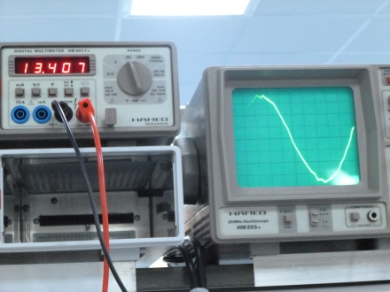
The supply actually outputs around 13.4 v or so which can be attributed to the tolerances of components used. Regardless of output being greater than 12v, I can still use it with the two different regulators I ordered from Rapid, the L7805cv 5v 1A TO-220 package regulator, and the LM723 adjustable voltage regulator in a 14-DIP package.
Both regulators have a maximum input voltage of 40v, so the 12v supply will be just fine. However the supply outputs an Alternating Current (AC) signal, this can be converted to Direct Current (DC), which is needed for most general electronics, by passing the supply through a device known as a Bridge Rectifier.
The Bridge Rectifier
Moving On . . .
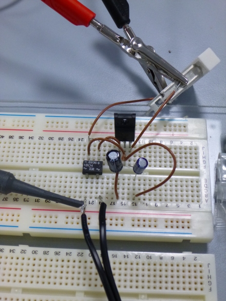
On my breadboard I first built the circuit to output 5v in order to power my Raspberry Pi.
This is a standard circuit found in the datasheet however C2 has a value of 100µF and C1 is equal to 10µF.
Oopps . . . Please do remember to put the capacitors the right way round, first time I’ve ever done it, but it turns out these capacitors don’t like 12v going in them the wrong way . . .
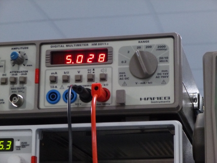
So after connecting the capacitors in the right polarity, and attaching a 7W 75Ω power resistor across the regulator’s output to load it, I attached the voltmeter to measure the output.
Using the 100µF and 10µF combination proved successful and outputted a solid 5.028v, however the datasheet recommends values of 0.33µF and 0.1µF. If anyone understands the reasons for the different values please do comment below because I am very curious as to why they both work.
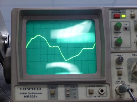
Additionally I would be interested to know why the AC signal of the 12v supply distorts as seen below when the supply is under load.
So yesterday I had no lectures, so instead of spending my time working on assignments that I don’t have, I decided to go into the engineering lab and prototype the MIC2941 adjustable voltage regulator circuit.
The datasheet for the 2941 contains a example circuit with maths to go with it. This circuit should be capable of outputting between 1.2v and 26v, perfect for what I want to do.
So in the lab I found the components I needed, and set to work.
In order to calculate the values on R1 and R2 I used the equation provided, Vout=Vref(1+(R1/R2)) re-arranging so that, R1/R2=(Vout/Vref)-1. With this I then had a ratio that I could scale to any values I wanted.
Due to the output voltage being limited to between 1.2v and Vin – 1v I chose to aim for a output of 15v initially, because the power supply unit’s (PSU’s) my university have on workbenches only go up to 20v.
So with that value in mind I calculated R1/R2 = 11.195 to 3dp, therefore I selected a pre-set 2kΩ for R2 and a variable 22kΩ for R1. In theory I should then be getting approximate output voltages of:
14.76v at full rotation 7.995v at centre point 1.5375v at low rotation
As seen in the video below, with the reference voltage at 1.2 – 1.3v (poor resolution on the power supply’s behalf) and 19.9v on the input, the output voltage seems to fluctuate between 6.6v and then back up to 15.1v and back down.
My plan in the next couple of days is to hock it up to the oscilloscope and investigate the input current, which was limited to 0.5A by the PSU.
Life at university is going well, however lab sessions are insultingly easy. They comprise of simply measuring the resistance, voltage and current with different combinations of resistors. Having said that I do understand that they are partially there as a method of learning how to use the test equipment that each workstation is equipped with.
I have been nominated as the Foundation Year course rep which means that people on my course are supposed to go to me with their problems regarding the School of Engineering and Digital Arts.
As well as that, I have joined the Caving Club, the Shooting Society, and become the Treasurer of the TinkerSoc, the University’s Engineers Society.
With the TinkerSoc we have plans for several big projects that I look forward to updating everyone on!
As I mentioned in my previous post, I am able to read the ID’s of both the cards that came in my kit, however these ID’s are raw. We can decode these into different formats.
By reading in the code byte by byte the code is read, by default, in decimal (DEC).
For those who haven’t met the different number base’s, in our normal day to day lives we use the decimal number system which is base 10, ie 10^0 = 1, 10^1 = 10, 10^2 = 100 . . . Base 10 only uses combinations of the numbers 0 to 9. Other common bases include:
Hexadecimal, base 16 ie 16^0 = 1, 16^1 = 16, 16^2 = 256 . . . Base 16 uses a combination of 0 to 9 and A to F to represent 16 digits.
Binary, base 2 ie 2^0 = 1, 2^1 = 2, 2^2 = 4 . . . Base 2 uses only two digits, 0 and 1.
So using this we can adapt what is sent using the Serial.print command by writing the value or variable we want to send, followed by BIN for binary, DEC for decimal, HEX for hexadecimal, as well as others that I haven’t covered.
so using
int val = 0; // variable to store the data from the serial port
void setup() {
Serial.begin(9600); // connect to the serial port
}
void loop () {
// read the serial port
if(Serial.available() > 0) {
val = Serial.read();
Serial.println(val,DEC/HEX/BIN); //use one Base as appropriate.
}
}
We can read the value in any base system supported by Arduino.
After a long wait my delivery arrived with the new RFID kit and 16×2 LCD.
So first thing to work on was the LCD, and what better to start with than “Hello World”! Having not used the Arduino for some time I started with the LiquidCrystal HelloWorld example and then worked from there.
#include <LiquidCrystal.h>
// initialize the library with the numbers of the interface pins
LiquidCrystal lcd(12, 11, 5, 4, 3, 2);
void setup() {
// set up the LCD’s number of columns and rows:
lcd.begin(16, 2);
// Print a message to the LCD.
lcd.print(“hello, world!”);
}
void loop() {
// set the cursor to column 0, line 1
// (note: line 1 is the second row, since counting begins with 0):
lcd.setCursor(0, 1);// print the number of seconds since reset:
lcd.print(millis()/1000);
}
After checking that I had everything working correctly using HelloWorld, I started experimenting displaying variables and changing the location of the cursor.
Next to work on the RFID module.
Not having an example to start with, I did a little searching online to find an excellent Instructables post. From this post I learned that with the RFID tx pin connected to the arduino’s rx pin, you can you the Serial.read() command to read the unique identifier.
/* RFID ID12 */
//RFID tx pin –> arduino rx pin
char val = 0; // variable to store the data from the serial port
void setup() {
Serial.begin(9600); // connect to the serial port
}
void loop () {
// read the serial port
if(Serial.available() > 0) {
val = Serial.read();
Serial.write(val);
}
}
Now that I was able to display text on the LCD and also read the values of the RFID tags, the next logical step was to combine the two together!
Now working on my own code, I set out to get the LCD asking for the card to be scanned, and then displaying the number of the card.
// put your setup code here, to run once:
Serial.begin(9600);
lcd.begin(16, 2);
lcd.print(“Please Scan Your”);
lcd.setCursor(0,1);
lcd.print(“Card:”);
}
void loop() {
// put your main code here, to run repeatedly:
if(Serial.available() > 0) {
// wait a bit for the entire message to arrive
delay(100);
// clear the screen
lcd.clear();
lcd.print(“Your Card is”);
lcd.setCursor(0, 1);
// read all the available characters
while (Serial.available() > 0) {
// display each character to the LCD
lcd.write(Serial.read());


 }
}
